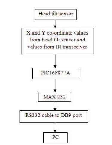
Figure 1. Flow of Working of the Module
This paper proposed an alternative for the use of computers by physically challenged and paralyzed people. It explains the basic idea of a Human machine interface which can be used to control the mouse using head-tilt [4], [5] and eyeblink [9]. The use of this mouse which is a emulating device does not required much energy since, it uses simple head movement and eye blink [1]. This device or Goggle uses three axes sensor for detecting the movement of the head according to which, the movement of the cursor can been done [8]. A photo sensor detects eye blinking [6]. The Infra Red (IR) transceiver consists of a 935nm IR transmitter and a phototransistor mounted on the same unit. This detects a strong increase in the reflected signal upon intentional long blink as compared to normal eye blink. This also uses palm vein pattern recognition as a biometric authentication for secured use of the computer. Palm vein authentication has a high level of accuracy since, it is located within our body and does not change over time. Hence, it cannot indulge in any kind of forgeries.
The aim is to develop a Human machine interface emulating the function of mouse for disabled or paralyzed persons, since the device relies on the user's head and eye movements[6,7]. It can be used even by a patient who is paralyzed from the shoulder downward.
Simple head movement does not require too much energy and neither does eye blinking. Therefore, user won't get tired of using this device. The authors have used three axes sensor to detect the movement.
When the head of the user is tilted up/down or left/right, the reading from the three axes sensor is compared to the Earth's gravity and the exact position of the cursor on the screen is determined. The difference determines the level of tilt [8], [3]. A photo sensor detects eye blinking. The Infrared transceiver consists of a 935nm IR transmitter and a phototransistor mounted on the same unit. This detects a strong increase in the reflected signal upon intentional long blink as compared to normal eye blink [9],[2]. The output of both the sensor is given to microcontroller PIC 16F877A.
After the signals are interpreted by the microcontroller, mouse instructions are sent to the computer. The processed digital information is transmitted to the PC (personal Computers) through the serial port.
Palm vein technology works by identifying the vein patterns in an individual's palm. When a user's hand is held over a scanner, a near-infrared light maps the location of the veins. The red blood cells present in the veins absorb the rays and show up on the map as black lines, whereas the remaining hand structure shows up as white.
This vein pattern is then verified against a preregistered pattern to authenticate an individual. As veins are internal in the body and have a wealth of differentiating features, attempts to forge an identity are extremely difficult, thereby enabling a high level of security.
The Figure 1 shows the Flow of working of the module.
Figure 1. Flow of Working of the Module
Figure 2 shows the process of identification model.
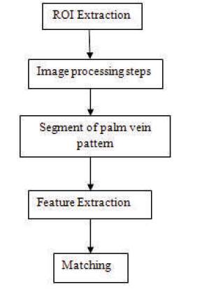
Figure 2. Process of Identification Model
This design is mounted on the user's head. It will collect the information regarding the mouse cursor position depending upon the user's head tilt and the information where to click from the eye blinking circuit. After processing the data, the Programmable Interface Controllers (PIC) microcontroller will be send certain signals to the computer's serial port via a RS-232 cable.
A back-end program running on the computer will interpret these signals and move the mouse cursor on the screen.
Palm vein recognition uses three algorithms:
The region to be worked is known as the Region of Interest (ROI) it is initially segmented and then binarized to convert the grayscale image into black and white image.
Then, histogram equalization is done to get the enhanced palm vein image. The input image processed is compared with the image in the database and the access to the system is provided in the case of perfect matching. Figure 3 shows the block diagram of complete unit.

Figure 3. Block Diagram of Complete Unit
The dual axis accelerometer contains on board singlepole switched capacitor filters. Because, the filter is realized using switched capacitor technique, there is no requirement for external passive components to set the cut-off frequency.
The output of the sensor is fed into the A/D (Analog to Digital) converter which is inbuilt in the PIC for the conversion of analog signal which the output of the sensor to digital signal which is fed to the microcontroller for further processing of data. The microcontroller works on the digital signal for the further processing of data. Here the authors used HD74LS90P to provide necessary clock pulse to the Analog to Digital Converter (ADC).
The PIC16F877A is in-built to ADC. The output of IR transceiver and accelerometer are detected by microcontroller after getting processed through A/D converter. The function of the microcontroller is to receive the data from A/D converter, process it and then send suitable signals to the computer's serial port. The tilt values are recorded in the form of X and Y co-ordinates which can be viewed in the LCD display. CCS compiler is used as a platform for programming. It is communicated to the PC through MAX 232.
It is a serial communication cable which is needed for communication between the computer and the micro controller. The RS-232 requires only 2 lines and a common ground.
The system uses three different softwares. One code is placed in microcontroller for transmission of information and click. Another program runs on PC to collect the data from serial port and mouse cursor.
Softwares used,
The 3 axis accelerometer with regulator ADXL 335 is a 3D sensor. It consists of X, Y and Z co-ordinates. It is a small, thin, low power, complete 3 axis accelerometer with signal conditioned voltage outputs. The product measures acceleration with minimum range of ±3g.
It can be used to measure the static acceleration of gravity in tilt sensing applications, as well as dynamic acceleration resulting from motion, shock, or vibration.
The authors used the two axes for sensing the X and Y coordinate values with reference to the Earth's gravity. The third axis for Z direction is terminated, since it is used to control mouse pointer movement on a 2D PC screen.
Visual basic software is used for coding to move the control of mouse pointer to the head tilt sensor.
The functional block diagram of the Head Tilt Sensor ADXL335 is shown in Figure 4. Bread board testing of accelerometer is shown in Table 1.

Figure 4. Functional Block Diagram of ADXL 335
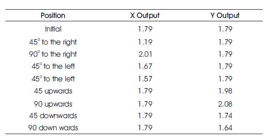
Table 1. Bread Board Testing of Accelerometer[10]
For the input mechanism, in order to detect the blink of the eye, the authors have needed to have a photo sensor which acts as a transceiver. Initially they selected OPB706, a reflective object sensor manufactured by Optek [10]. The OPB706 consists of an infrared light emitting diode and an NPN silicon phototransistor mounted side-by-side on parallel axes in a black plastic housing. On the OPB706 the LED and the phototransistor are molded using dark infrared transmissive plastic to reduce the ambient light noise. The phototransistor responds to light from the emitter when a reflective object passes within its field of view of the device.
Accelerometer is used for the determination of the degree of user's head tilt. Accelerometer uses the force of gravity as input vector to determine orientation of object in space. When oriented parallel to earth's surface, it can be used to detect the relative tilt of head. One of the most popular applications of the MMA7260Q is the tilt measurement. The accelerometer is most sensitive to tilt when its sensitive axis is perpendicular to the force of gravity, i.e, parallel to earth's surface. At this orientation its sensitivity to changes in tilt is highest. Bread board testing of Blinking detector is shown in Table 2.

Table 2. Bread Board Testing of Blinking Detector[10]
The accelerometer consists of a G-cell which senses the change in acceleration when the head tilts. G-cell consists of two capacitive sensing cells, formed using 3 beams, where the middle beam is movable thus these forms 2 back-to-back capacitors. The pin number 1 and 2 of the IC are used to select particular sensitivity.
It acts as an intermediate between the back end and the front end system. The IC MAX232 is an electronic system which converts signals from a serial port to microprocessor circuits. Pin diagram of IC MAX232 is shown in Figure 5.

Figure 5. PIN Diagram of IC MAX232
The MAX232 requires 5 external 1µF capacitors. These are used by the internal charge pump to create ±10 volts. microprocessor circuits.
The easiest way to get these values is by using the MAX232. The MAX232 acts as a buffer driver for the processor. It accepts the standard digital logic values of 0 and 5 volts. It converts the digital logic values to the RS232 standard of ±10 volts. It is also helps to protect the processor from possible damage from static that may come from people handling the serial port connectors.
The Proposed System was first started with the construction of power supply unit. Then the head tilt sensor was build up on the printed circuit board. The three axes sensor IC ADXL 335 is used due to the unavailability of two axis sensor. The IC being extremely small, it is soldered on a Printed Circuit Board (PCB). After the completion of soldering, the testing was done and the verification was done at the outputs within the range of specification. After testing the IC by tilting it in X and Y axis, it is mounted on to the main setup. Then the IR transceiver is fitted on to the board.
A working prototype of the Head tilt sensor which perform mouse pointer movement is functioning successfully in all aspects. This module uses a three axes sensor to detect head movement. When the head of the user is tilted up/down or left/right, the reading from the axis sensor is subtracted from the pre defined reference point. The reference point is the Earth's gravity. The difference determines the level of head tilt. The blink detection circuit was designed successfully. By placing the transceiver close to the eye, the circuit was tested satisfactorily on a breadboard.
The output of the sensors are given to the microcontroller. The analog values are converted to digital values by PIC16F877A, since it has an ADC module which is built in it. After the signal is interpreted by the microcontroller, mouse instruction is send to the computer. The processed digital information is transmitted to PC through the serial port.
The hardware components have been successfully implemented, tested and debugged. The software was executed and the outputs were obtained. Then the results were verified.
The hardware components are soldered on a PCB Board and the Head tilt sensor is interfaced with the microcontroller PIC16F877A. Snapshot of PCB Board with soldered components for the mouse movement is shown in Figure 6.

Figure 6. Snapshot of PCB Board with Soldered Components for the Mouse Movement
Then the IR Transceiver circuitry is also added to the set up and the complete set up is made. PCB Board with complete transceiver set up soldered is shown in Figure 7.

Figure 7. Snapshot of PCB Board with Complete Transceiver Set up Soldered
This paper has implementation of mouse pointer movement using head tilt of the user. By using this, the mouse pointer can only we moved and it cannot be used to select the things on the computer screen. The selection of things can be done using the eye-blink of the user. Since this project has maximum application by the physically challenged people, the eye-blink can be used to select the objects. A photo sensor detects eye blinking. The Specification and the Look-up tables for X axis and y-axis are shown in Tables 3-6.

Table 3. Specification of X-axis[10]
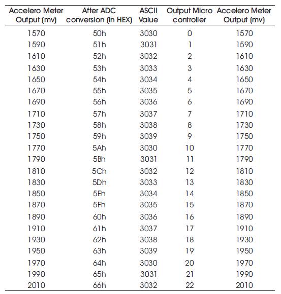
Table 4. Lookup Table for X-axis[10]

Table 5. Specification for y-axis[10]

Table 6. Look up Table for Y-axis[10]
The infrared transceiver consists of an IR Transmitter and a phototransistor mounted on the same unit. This detects a strong increase in the reflected signal upon intentional long blink as compared to normal eye-blink. The output of both the sensor i.e., the Head tilt sensor and the photo sensor are give to the ADC input port of the microcontroller. The processed digital information is transmitted to the PC. Then the complete mouse action of cursor movement and selecting objects can be implemented.