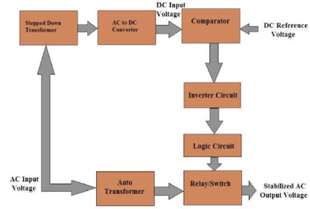
Figure 1. Block Diagram with Different Applications of Automatic Voltage Regulator
The aim of this study is to implement better heuristics in solving the issue of hysteresis in design of an automatic voltage regulator to bring significant precision and resolution. In rural areas, voltage provided continues to be lesser than specified that does not provide the necessary feed to the electronic circuits where it may be required. This puts sophisticated electronic devices such as computers and other devices at substantial risk. In this proposed work simulated the entire automatic voltage regulator section in Multisim is simulated and hereby proposed a signal conditioning circuit that can resolve the issue of identifying the role of a linear circuit design and a small signal analyzer for amplitude frequency characteristics. In order to restore this circumstance, this research identifies the mechanism for stabilizing a diverse range of input voltage from the lowest to the highest value by discussing a measuring circuit that drives the transformer from either the main side to the secondary side repeatedly. This study therefore proposes an alternative solution by developing an Automatic Voltage Regulator (AVR) involving design of different controllers and systems that operate within the monitoring range. The digital AVR requires certain computational modifications based on certain parameters and features.
It is feasible to divide the analysis of synchronous generator input method into voltage regulation and velocity control. Synchronous generators generate electrical power in many power plants. The synchronous generator utilizes a self-generating transformer with the bridge rectification system to develop the output voltage. The synchronous generator excitation system (Kundur, Balu, & Lauby, 1994; Machowski, Bialek, & Bumby, 2011) constituted of alternator, controller, voltage sensor, load compensation, power system voltage conditioner, security and limiter as seen in the Figure 1. In the presence of disturbances, both power characteristics contribute to the machine's stabilization. The stable activity of generators involves a reliable monitoring system set. There are different techniques of managing a synchronous generator, and stability depends on the device type, operation and working conditions. Reference voltage and output feedback from either the regulator is defined by voltage sensor, load compensator, security and limiter, and stabilizer for energy generation. Power quality issues that are commonly faced by manufacturing processes include transients, sags, swells, surges, outages, harmonics, and impulses differing in voltage size or magnitude. AVR is suitable for regulating the output voltage in variable velocity device appliances through field excitation. The generator terminal voltage is given to the AVR for making comparisons to a reference value and producing an error signal. The function of AVR tries to follow: to achieve this reference power output, the AVR relates the terminal voltage of the generation system with the voltage of a preset response.
Figure 1. Block Diagram with Different Applications of Automatic Voltage Regulator
A sinusoidal pulse width modulation (SPWM) method for managing unpredictable input AC voltage is characterized in (Tarchanidis, Lygouras, & Botsaris, 2013; Nawaz & Arbab, 2013). Tarchanidis et al. (2013) proposed a microcontroller-based technique which controls a stabilizer AC / DC / AC. Zhou, Ya, and Zhao (2014) proposed a novel design of a 3-phase AC voltage regulator with Silicon Controlled Rectifier (SCR) trigger circuitry based on a particular microcontroller unit. The proposed design adopts SCR as energy devices that are commonly used in industrial purposes. Attia (2015) proposed an AC and DC voltage control systems. These studies highlight different techniques of controlling AC and/or DC voltage (Hamza & Bonneya, 2019) and connecting loads with / without PWM technique (Nagai & Itoh, 2019). In any suitable fuzzy logic and also the concurrent system on neural network modelling (Schaef et al., 2019; Sisworahardjo, El-Sharkh, & Alam, 2008) it can perform well without needing a precise model of the actual scheme. but the stabilization of the closed system is not assured unless artificial intelligence is used (Mathur, Rajpurohit, & Srivastava, 2018) or intelligent monitoring approaches (Bhatt & Bhongade, 2013) which may be robust and give high end output. The work in Attia (2015) proposes a new three step AC voltage regulator based on one step down transformer, this study is characterized by simplicity and low cost because of the dependence on one transformer.
To obtain regulated and stabilized load-side output voltage, feed supply and switches are connected in primary and secondary simultaneously to a cross-tapped transformer. A comparator circuit plays a key role in assessing the adjustments which take the power from the input to the steady voltage charge through the supplementary touch.
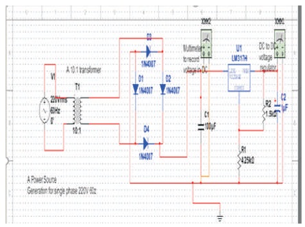
Figure 2. Automatic Voltage Regulator Circuit
The integral expression contributes to the control action unless the error has remained intermittently if the error changes constantly with time, the derived term is a response against the control action. LM324 has been used for a comparator circuit matching the DC voltage variable detected by step down voltage (220 V AC-12 V DC) of the power distribution board with the reference voltage (12 V DC). Some components of the digital AVR must be managed to keep analog in fact necessary to provide the signal conditioning service. The modeling circuit generator and excitation may be used for digital AVR testing to develop the DC voltage generator. This section of varied resistance is connected with a linear load circuit, which is grounded to the earth and based on the value of the resistance in the section a DC voltage is extracted at the output. In the presence of disturbances, both power characteristics contribute to the machine's stabilization. Diode D2 is pushed forward into the positive half cycle, and if connected, the current ID2 runs through and across cluster. It flows into the forwarding bias diode D4 through return path and approaches the generator terminal's negative polarity. This is obtained by matching the voltage with a target voltage and making significant adjustments in the field current to bring the output voltage equal to the required value from the difference. This circuit is designed for getting 12 volt DC stable power supply; here IC 7812 is used, which give the fixed 12 V DC. It is used as a reference voltage of comparator circuit and for the biasing of LM324. In the mechanical aspect, a wide variety of AVRs varies from vibrating to contact based regulators and carbon piles-based regulators work. They are substituted by continuously acting electronic regulators, but, that are much faster and does not have dead bands.
By mixing ATmega 8 microcontroller in order to implement a digital AVR and employing op-amp as its signal conditioning with circuit synthetic trigger circuit (Mukti, Wijanarko, & Muqorobin, 2016) accurate signal acquisition, high quality and robust thyristor trigger pulse anti-interference capability and output isolation is achieved (Hoque, 2014).
Automatic voltage regulators measure two units which are the standard measurement and the unit of regulatory control. The measuring unit's function is to classify a transition in the automatic voltage regulator's input or output voltage and to produce a signal to operate the regulating unit. The automatic voltage regulator or stabilizer is fully automated, offering protection from raised voltage for any protective electronic equipment. For a suitable main energy supply, synchronous grid continuous voltage at the generator terminals is essential. Different adverse variables (frequency, load, power factor, and temperature increase) can affect the terminal voltage, so that separate monitoring equipment is needed to support the voltage stable even when these disturbing conditions impact it. The voltage across the resistance R1, VR1 = 1.25 V and the voltage across R2, VR2 = 1.25V x (R2/R1). Since the output voltage is: Vout = VR1 + VR2, then
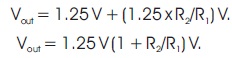
If we modify the R2 resistor value (variable resistor), the Vout voltage is modified. Here, R1 = 240 ohms and R2 = 5K or 3K (potentiometer). The filtering capacitor acts as a bypass resistor that reduces the transients in the negative direction.
The quiescent current is the current used by the regulator to power itself, and as a function of the input voltage. This is demonstrated using graph plotted for the distinct variants of the regulator. The filter capacitor is a low pass filter and it must be somewhat sizeably large depending on how large the output ripple is. AC Mains that is rectified constantly modifies the voltage, so having a huge Condenser filter section keeps the voltage control board input constant, but during the segments of time when the AC waveform is below the voltage stored by Condensers the load will discharge the capacitor. It has been noted that AC V-max is V-root-mean-squared/.707 instead of 1uF at a voltage rating that exceeds the prerequisite voltage requirements. If the circuit assumes that the input voltage is DC and has little ripple voltage (because of the very small filter cap value of 1uF) but it does not have to filter as much and the filter limit for ripple which can arise due to transients are the very small (but non-zero) direct current. Existing field monitoring with maximum source field current is used to avoid control action allowing field current to exceed its maximum (Mukti et al., 2016; Haque, Hossain, Ali, & Sheikh, 2011). It is necessary to understand that only D2 and D4 are biased forward in this phase to allow ID2 and ID4 currents along the loop back through the return path to the transformer's negative polarity.
The characteristics to be accommodated in the embedded system are considered in the digital AVR design (Haque et al., 2011). The least difference in voltage switching and backing from comparator outcomes in low hysteresis in overall AVRs causes swift switching. This is solved by a feedback link in the selector from output to varying resistance interface. The module's SHDN input can be lowered to place the board in a low-power state which is typically very less than 2 μA.
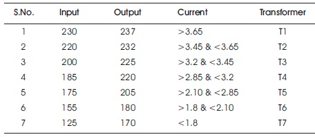
Table 1. Recorded Data for Input and Output Current Characteristics
This method allows the adaptive controller to be commenced efficiently and eliminates transient induced oscillations.
A time response analysis for the overall circuit is performed and the circuit output is shown in Figures 3 and 4.
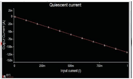
Figure 3. Simulation Output for the Queiscient Current
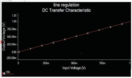
Figure 4. DC Transfer Characteristics
It allows the parameters to converge flawlessly and at the same time providing a stable output. Concern locations include terminal voltage fluctuations, unreasonable fluctuations in frequency or voltage, or significant deviations from the set point. The behavior may lead to a decrease from extrinsic faults on the scheme.
The AVR compares the generator terminal voltage with a pre-set source voltage. If the generator terminal voltage is below the reference voltage, the AVR will improve DC voltage across the generator's field. Regulators can be manually or automatically controlled. Manual control can be conducted by tap-changing switches, a variable auto transformer, and an induction regulator. From the above case, the consequent voltage is sensed by a voltmeter linked at the output, whereas a human chooses and rectifies the operation. A device functioning within a relatively still marginal voltage range in 10% would be regarded to have a relatively small sensitivity to voltage or voltage fluctuations. A device that actually works when the voltage level stays within 5% (or less) of marginal voltage will be considered sensitive to clock speed or fluctuations.
Proper measures should be taken to encourage market owners to develop this type of regulatory framework and deliver at a reasonable price point to the user. This framework ensures that input fluctuations of 150V-273V AC to the tolerable range of 215-237 volt AC output are enforced here. The output of frequency sensor is ranges from 0 V to 10 V.
By incorporating several taps on the secondary end of the auto generator and relays, a unique automatic voltage regulator which can regulate 80 V AC - 350 V AC input voltage to a stable voltage of 220 V AC can be generated. Voltage regulation is done automatically by adding many secondary taps. This design ensures input variation of 150 V - 273 V AC to the tolerable 215-237 volt AC output range. The voltage selection of 100 V AC - 350 VAC to a stable 220 VAC voltage can be controlled automatically by raising taps on the primary side of the auto generator and relays. This circuit offers better response when the load changes via system operation.