Figure 1. Tap Number Counting in Forward Direction
In Very-Large-Scale Integration (VLSI), the main challenges for the researchers are to reduce the power dissipation by the devices. In this paper, the authors have proposed a modified version of the Linear Feedback Shift Register to meet the specific output. The power consumption can be reduced by deactivating the clock signal from the flip flop to design test pattern generator during testing power. The LFSR pseudo-random test pattern generator is used in the testing of the ASIC chips, which is used to generate the random sequences of the desired pattern generator. This paper will help in the reduction of additional test inputs used for the ASIC. The test pattern is generated in such a way that the component requirements can be reduced.
In VLSI design, there are so many benefits of using BIST techniques, these benefits are testing and lower speed that provides better testability and also improves the cost requirements of ATE. Mostly the BIST technique is used to find the faulty components of any integrated circuits, which is a discrete fourier transform technique (Zeng et al., 2007). The main challenge of VLSI design is its cost, performance, testing, reliability, and power consumption. From the above challenges, the power consumption is the major one. So the power optimization is required. Some more factors also affect this technology, such as packaging, testing, etc.
The challenges are,
1. Cost of testing that cannot be scaled.
2. As the circuit complexity increases, the efforts of generating test factors are also increased.
In digital circuit, there are two main sources on which the power dissipation depends, i.e. static power dissipation and dynamic power dissipation. These are the two classifications in which static dissipation depends upon the leakage current which are very small in the circuit, whereas the dynamic power dissipation depends upon the switching, clock frequency, and the supply voltage. These are the factors on which most of the power are consumed and this leads to the degradation of the performance of these circuits. In comparison to the normal mode, most of the power are consumed during the testing (Muttoo and Abdulsattar, 2012).
In this paper, the low power consumption based system has been proposed to design. In this design, the principle of Linear Feedback Shift Register is used.
Various methods has been already proposed to overcome the power dissipation of the device during testing. Brock (2006) initially developed a fault model and used an Automatic Test Pattern Generation (ATPG) algorithm and finally the test pattern is generated to get the desired fault coverage. At higher level, the test pattern generation has various advantages than the gate level (Ajane et al., 2011). For sequential circuits the low power test pattern generation has been proposed (Tehranipoor et al., 2005). In this design method, a redundancy is introduced during testing and without affecting the fault coverage, the power consumption gets reduced. Ahmed et al. (2004) developed an approach, where the number of transition in scan chain is reduced along with the number of bits generated by LFSR reseeding.
To generate a low power system, random test pattern generator is used. For BIST application, a low transition LFSR for BIST is proposed. This method reduces the average and peak power of the circuit during testing.
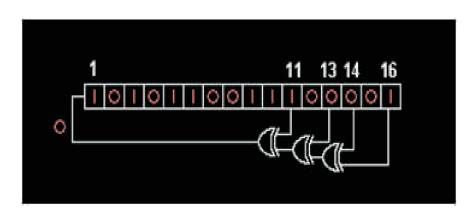
In the Fibonacci LFSRs technique, the feedback tap number is represented by white color, which is used to represent the primitive polynomials. The possible states for 16 bits LFSR is 65535, including the states containing zeros. The feedback tap is represented by white color which is shown in Figure 1. Output is the rightmost, but in LFSR, the respective tab has a sequential reaction with the output and the output produced is feedback to the leftmost bit of the LFSR (Haridas and Devi, 2011). This bit sequence is known as output stream. The tap number counting in forward direction of the Linear Feedback Shift Register is shown in Figure 1.
Figure 1. Tap Number Counting in Forward Direction
PN sequence is produced by a maximum length LFSR till it contains all zeros. Using the XOR based comments in an LFSR, one can also use XNOR. This function is an affine map and not a linear map, but it results in an equal polynomial counter, whose state of the counter is a complement of the state of an LFSR. A notion with all ones is unlawful whilst using an XNOR remarks, same as a state with all zeros is illegal with the usage of XOR. This country is considered unlawful due to the fact the counter would stay "locked-up" on this country. The series of numbers generated by using an LFSR or its XNOR counterpart can be taken into consideration as a binary numeral device using legitimate Gray code or the binary code. The association of faucets for remarks in an LFSR may be expressed in finite discipline mathematics as a polynomial mode. In this approach the coefficients of the polynomial have to be ones or Zeros, which is considered as the remarks polynomial or characteristic polynomial (Prasada Rao et al., 2013).
In this implementation at every steps or shifting, the contents get modified which is done by using binaryweighted value. This modification is based on the modulo- 2 math. Its weight is just reverse or opposite than the other method such as Fibonacci weight method. It is also possible in this method to obtain same output of the two LFSR implementation. This method is faster than the Fibonacci LFSR method and implementing this in hardware requires less logic circuits and due to this, Galois LFSR is much better than Fibonacci LFSR (Gunavathi et al., 2006). For 16 bits Galois LFSR, the tap is also represented by the white color, but the counting of number represents the tap is reverse. The numbering is shown in Figure 2.
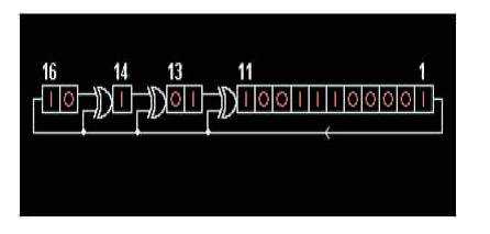
Figure 2. Reverse Counting of Tap Number
Binary Galois LFSRs can be generalized to any q-ary alphabet 0, 1... q-1. In non-binary, the XOR issue is generalized to addition modulo-q, and the feedback bit is expanded by using a q-ary value, which is consistent for every unique tap point. In the binary case, the comments is accelerated by using either 0 or 1 (Gunavathi, et al., 2006).
This technique will help in the reduction of cost equipments. The major problems associated with the previous techniques are test generation problems and Gate to I/O pin ratio.
Due to the presence of large number of gates in design of VLSI circuits, it requires more time to obtain automatic test generation, i.e. this test generation can take from few weeks to months to perform any computation. Due to this, its handling becomes more complex for external tester, which is also cost effective (Kaur and Baja, 2012).
BIST architecture typically consists of the following units,
The Test Pattern Generator (TPG) in BIST is presented in Figure 3.
The BIST architecture helps in generating test pattern for Circuit Under Test (CUT). This consists of either microprocessor or any other dedicated circuit, which can perform the required task. These patterns generated are either pseudo random sequence/ numbers or any other deterministic sequence. In this paper, the authors have used a Linear Feedback Shift Register to generate the random number. The architecture of LFSR is shown in Figure 4.
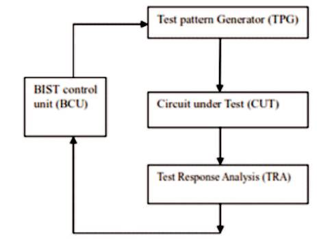
Figure 3. Test Pattern Generator in BIST
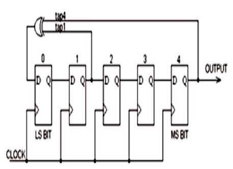
Figure 4. The Architecture for LFSR
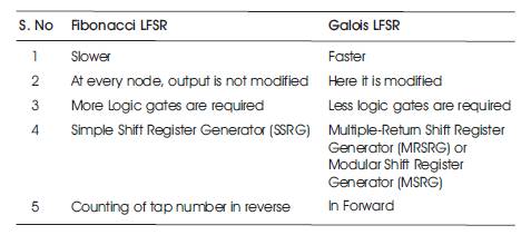
Table 1. Comparison Table
This will give the error by checking MISR output by using TRA and verifying with the input of LFSR
This control unit is used to control the operation of shifting and modulo-2 math. In both the modes, i.e. test mode or normal mode, this controller can easily control all the operations. This is done by controlling MISR and TRA. This will indicate the error signal in terms of interrupt. This interrupt can be cleared using clear signal.
These are the circuits or chips in which the operation is being performed, i.e. BIST is applied. BIST is used for testing stuck at zero or stuck at one if error occurred.
In this paper, a comparison is done between Fibonacci LFSR method and Galois LFSR. It is found that the power requirement in Galois LFSR is less in comparison to Fibonacci LFSR technique. The Galois LFSR is faster since it requires less number of logic gates than the Fibonacci LFSR Technique.
Expression of giving thanks are just a part of those feelings which are too large for words but shall remain as memories of wonderful people with whom the authors have got the pleasure of working during the completion of this work. They are grateful to Shri Shankaracharya Institute of Professional Management and Technology, Raipur which helped them to complete this work by giving encouraging environment. Authors would like to express their deep and sincere gratitude to the supervisor, Assistant Professor Mr. Ankit Singh. His wide knowledge and his logical way of thinking have been of great value to them. His understanding, encouraging, and personal guidance have provided a good basis for the present work.