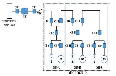
Figure 1. MG Layout
This paper summarizes the overview about the microgrid and the adaptive protection of the microgrid by using advance relay. Microgrid is a combination of interconnected loads, distributed energy resources (like PV cell, combine heat and power, wind energy, small hydro, etc.), and the storage unit (i.e. battery) within clearly defined electrical boundaries that acts as a single controllable entity with respect to the grid. In adaptive protection scheme, relay changes its settings automatically when microgrid changes its operational state because the level of fault current is different in both working mode. The value of fault current is high in grid connected mode so the relay settings must be high and the fault current value is less in island mode, therefore the relay setting is less compared to the grid connected mode. Microgrid can operate in two modes, i.e. grid connected mode and islanded mode. A microgrid which has three switchboards (each switchboard has a generation unit and load) is designed and adaptive protection is implemented on it in Matlab/Simulink. The source of energy is wind in the entire generation unit and load is resistive of same power. Two fault locations have been taken into account in both the operating modes and the smallest portion of the load has been disconnected during fault time. Results of six cases have been discussed in both the fault locations and the status of microgrid circuit breaker is shown in the event table.
A Microgrid is like a smaller utility grid or power grid. It has a light load as compared to the utility grid. The major difference between MG and utility grid is that MG has its own generation resources (such as wind turbine and photovoltaic power system, etc.), energy storage unit, and load. In other words, it can be say that MG is a discrete energy system consisting of MGR and load. One of the major advantages of the MG is that it can transfer power to the utility grid during peak load or grid failure and it can take power from the utility grid during normal load [9].
During the previous years, the concept of MG has increased as an incredible way of integrating sustainable energy sources in the electric system. The main advantages of the MG is that it supplies power locally, reduced grid investment and operational cost, reduces losses, increase reliability, and share the peak load [2].
There are two operating modes of MG [4], first one is the grid connected mode and second is the islanded mode. In grid connected mode, MG is connected to the main grid, in this case the MG Disconnecting Device (MDD) is closed. In this mode, main grid can supply or take power from the MG. When main grid supplies power to the MG, the entire load is connected to the main grid and the generation units of the MG will not work. In case of peak load, the generation unit of the MG is active and supplies power to the main grid. In case of emergency and power shortage, MG works in the islanded mode. The MDD is open and entire load is connected to MGR. Benefit of islanded mode is that it reduces the transmission losses [2].
The essential features of MG are,
It is necessary to protect the MG from any kind of fault. There are many techniques to protect the MG like Differential Protection, Distance Protection, Overcurrent Protection, Adaptive Protection, etc. [7]. Adaptive protection is the most successful method of the MG protection [6].
This paper is ordered as follows. Section 1 describes the objectives of the study. In section 2, the possible fault locations of MG are discussed while in section 3, a description about adaptive protection of MG, and in section 4, simulation of adaptive protection is described.
There are many protection schemes (like differential, distance and over current protection) to protect the microgrid from any kind of line fault or disturbance. The major problem to protect the microgrid is the fault current level. The value of fault current in grid connected mode is approximately 9 to 10 times of the islanded mode. Due to this, relay setting is different for both the working mode and in case of adaptive protection, the relay setting should be changed automatically.
The main objective of this research paper is to propose a microgrid model with the generation unit and adaptive protection is implemented on it. This research paper will give an idea to other researchers about the MG and also boost up to protect the MG by using other techniques.
Figure 1. MG Layout
Fault is the unnecessary disturbance that occurs in the system, which is due to the abnormal flow of current in the circuit. In MG possibly two faults occurs, first is at load end and second is at the bus bar. These two faults occur in both the modes of MG. Both the faults in both modes are discussed below [1].
When the fault (F1 ) occurs between the two circuit breakers then MG protection tries to remove the smallest portion from the circuit by using CB 4 and CB 8. Fault current pass through the CB 4, so CB 4 is opened due to high value of short circuit current supplied by main grid. If CB 4 fails to trip then fault must be cleared by CB 3 of switchboard (SB) A. In case of tripping failure of CB 4 then CB 3 works as a backup protection of CB 4. This delayed fault tripping unnecessarily disturbs the load 1. If CB 3 works then only load 2 and load 3 will be affected, but if CB 4 fails to trip then whole MG will be affected.
When the fault occurs at the load end (F2 ) then high value of fault current is delivered from the main grid. The CB 14 or fuse will isolate the faulty load (load 3) only and in case of tripping failure, CB 13 will operate because it acts as a backup protection of CB 14.
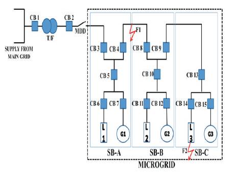
Figure 2. Fault Location in MG
In islanded mode, the MDD is off, MG is isolated from the main grid. Any of the MGR will work and supply the power to the loads. If the fault (F1 ) occurs at the bus bar, then a low value of fault current will flow in the MG. In case of islanded mode, non-directional relay is used instead of directional relay because fault current can flow in any direction. In case generator 2 is working and fault occurs at bus bar then the smallest portion is disconnected by the CB 4 and CB 8. Firstly, the CB 8 will operate and in case of tripping failure, CB10 will operate because it acts as a backup protection of CB 8. If CB 8 will trip then only load 1 will be affected, but if it fails to trip then both load (load 1 and load 2) will be affected.
If the fault (F2 ) occurs at load end then low value of fault current is supplied by MGR (generator 2). The CB 14 or fuse will operate first and if failure in tripping of CB 14 then CB 13 will operate. This will disconnect the faulty load (load 3) only.
Adaptive Protection System can solve many problems which usually happen during fault conditions. Major problem of the MG during the fault condition is the value of fault current. The value of fault current in the grid connected mode is very high than the islanded mode [5]. So there is a problem with the relay settings. This problem is removed by two ways, (i) install a source of high short circuit current (e.g. flywheel or super capacitor) to trip CB of blow fuses with the same setting of the grid connected mode, (ii) install a adaptive MG protection which reads the working mode of MG and change the relay setting with change the value of fault current [7]. It is necessary to change the relay settings when the MG changes its working mode because it is easy as compared to the first method. Adaptive protection is “an online activity that changes the desired protective response to a change in system situations or necessities in a timely manner by means of externally generated signals or control action” [8].
The working of adaptive protection is explained by flowchart method as shown in Figure 3. Firstly, data has been collected from the control unit and if there is any disturbance then find the fault location (internal or external fault). If the fault is the internal fault (in the MG) then relay will sense the working mode of the MG and according to the working model, relay will change its setting and remove the fault. After removal of fault, MG will start working in healthy condition and if fault is not removed then again check the data from the control unit.
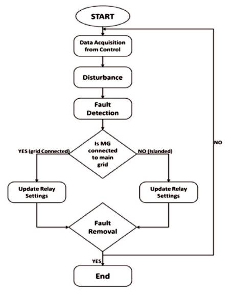
Figure 3. Flowchart of Adaptive Protection for MG
Figure 4 shows the relay circuit which is used to detect the MG operating mode and changes the relay setting with regard to the MG operating mode. Firstly, the MDD signal is multiplied with the grid connected setting which is found by the off line analysis then the output of the multiplier is given to the maximum block with the islanded mode setting. Obviously, in grid connected mode, the grid connected setting is more than the islanded mode setting, then this value is compared with the rms value of fault current. When the fault current is more than the set value, relational operator gives the off command to the CB. Output of relational operator is passed through the filp-flop, which is used to remove the toggle condition of the CB signal. If flipflop is not in the circuit then CB will not open during the fault period and CB will toggle in fault duration. CB is closed manually after clearing the fault. In the islanded mode, signal from the MDD is 0 so the islanded mode setting is higher than the grid connected setting. Now islanded mode setting is compared with the rms value of fault current and relational operator gives the off command to the CB and again ON command is given manually [10]. By using two different analysis, the relay setting can be changed [6].
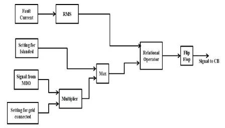
Figure 4. Relay Circuit
In off-line analysis, one can create a meaningful MG configuration and the status of MGRs (on/off) in a table, called event table. A structure of event table is shown in Table 1. Every record in the event table has equal number of elements to the number of monitored CBs in the MG (some CBs may have higher importance than others, e.g. the central CB which ties MG and main grid) and is binary coded, i.e. element=1, if an equivalent CB is closed and 0 if it is open. Then fault current is passing through all observed CBs by using simulation short-circuit (3 phase, 2 phase, single phase, etc.) in different locations of the MG. Fault current is passed at different location for different MG mode and the results (direction and magnitude of fault current and CB status) are saved in the event table.
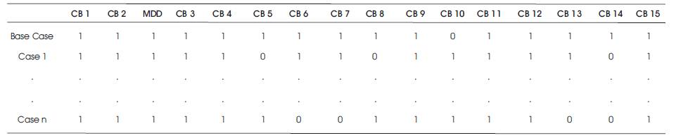
Table 1. Structure of Event Table
By using event table results, suitable settings for each relay and for each MG mode can be calculated in such a way that the MG is guaranteed protected. These settings of the relay are grouped into a table called action table which has similar dimension as event table.
Figure 5 shows the operation of online analysis. In this operation, the relay monitors the current state of the MG. This procedure runs sometimes or is activated by an event (tripping of CB, protection alarm, etc.). The status of CBs is recorded in the status record which has same dimension as a single record in the event table. The status record is used to recognize a corresponding entry in the event table. Finally, pre-calculated relay settings from the corresponding record in the action table retrieves and uploads the settings to on-field relays.
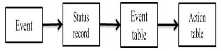
Figure 5. On-line Adaptive Protection
The same MG setup as shown in Figure 1 has been designed in MATLAB simulation and run for 1 second. The MG consists of three SBs, each SB has its own generation and load as well. SB A and SB B have five CBs and SB C has three CBs for the protection purpose and isolates minimum portion of the MG in fault condition. All the CBs are externally switched by the relay. Relay consists of multiplier, logical operator, etc., as shown in Figure 4 and sends the command to CB near to the fault location. All the generations are wind generator in the MG, which are used to supply the power to the MG in case of islanded mode and to the main grid in case of peak load or in emergency.
In this model, the authors took two fault locations, one is at load end and another is at bus bar as shown in Figure 2. There are three possible fault conditions in the designed MG, (i) fault occurs at load end, (ii) fault occurs at bus bar, and (iii) simultaneously fault occurs at both the locations. All condition can be occurred in both MG operating mode, i.e. grid connected and islanded. Fault is Line to Line to Line to Ground (LLLG) fault at both the ends and fault duration is 0.4 second from 0.3 sec to 0.7 sec. Fault currents are shown in Figures 6 and 7. The value of fault current in grid connected mode is much higher than the fault current in islanded mode. The average value of fault current in grid connected mode is around 3400 Amp and the value of fault current in islanded mode is around 600 Amp in the designed model.
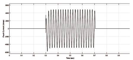
Figure 6. Fault Current in Grid Connected Mode
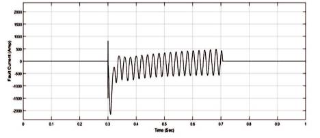
Figure 7. Fault Current in Islanded Mode
Phase voltage and current of the entire load are shown in Figures 8 and 9. Figure 8 is for the fault at load end (in both operating mode) and Figure 9 is for fault at bus bar. When the fault occurs at the load end in both modes, then only load 3 will be isolated from the supply and load 1 and load 2 will work in healthy condition. At 0.3 sec, the fault occurs and relay sends the OFF command to the CB 14 and CB will take approximately 0.186 seconds. At 0.8 sec, CB 14 is closed again manually and load 3 connects with the supply.
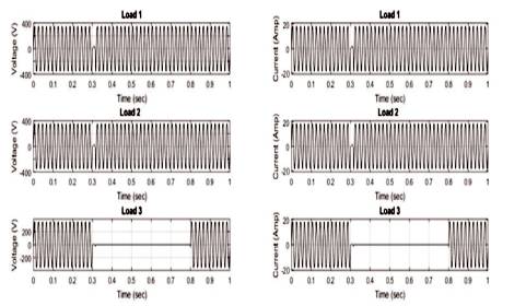
Figure 8. Branch Current and Voltage when Fault at Load End
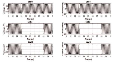
Figure 9. Branch Current and Voltage when Fault at Bus Bar
When the fault occurs at the bus bar in grid connected mode, then the CB 4 will break the circuit and isolates the load 2 and load 3 from the supply and at 0.8 sec, CB 4 is closed again manually. Figure 9 shows the phase voltage and current of entire load of MG when the fault occurred in the islanded mode, but in this condition, generator 1 is active and other 2 generators are not working. Figure 8 will be same for all the generator, but there is change in Figure 9. If generator 2 or 3 is active, then only load 1 will be isolated from the supply and load 2 and 3 will work in healthy condition.
Figure 10 shows the fault at both location in grid connected mode. In that case, fault 1 is active for 0.5 to 0.7 sec and fault 2 is active for 0.3 to 0.6 sec. Load 1 is unaffected for that condition and other two loads are affected in this condition. Load 3 is affected upto 0.6 sec, but due to the fault at the bus bar, load 3 is affected upto 0.7 sec and both CB are closed manually at 0.8 sec. When this condition occurs in islanded mode (for generator 2), then load 2 is unaffected and load 1 and load 2 are effected.
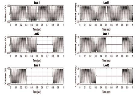
Figure 10. Branch Current and Voltage when Fault at both Locations
Table 2 shows the event table of different cases of fault that occurs in MG and its operating mode. It shows the status of CB (i.e. “1” for closed and “0” for open) when the fault occurs in MG. Case 1 is for the fault at the load end in the grid connected mode, in that case MDD is closed and all the generators are open (i.e. CB 7, 12, and 15) and CB 14 is open through the relay command to isolate faulty load. Case 2 shows the fault at bus bar in grid connected mode, in which CB 4 isolates the faulty load from the supply. Case 3 is for fault at both the locations, and then CB 4 and 14 isolate the load from supply. Cases 4, 5, and 6 are for the islanded mode, in these cases, MDD is open and one of the generators, supply power to the load. Cases 4, 5, and 6 are the faults at load end, bus bar, and both locations, respectively. Generators 1, 2, and 3 are active for cases 4, 5, and 6, respectively.
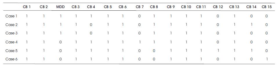
Table 2. Event Table of Different Cases
In this study, the triple line fault has been taken into the consideration and the proposed model is protected by the adaptive protection scheme without using any kind of controller. It will disconnect the faulty load only from the supply in both the working modes. The adaptive protection scheme is most suitable for MG protection. It can protect MG in both the working modes without manual interference. It can change its relay settings with the help of externally generated signal from the MDD. Due to this feature, it is most recommended for the MG protection.
It is recommended to other researchers that they can consider other faults like single line to ground fault, double line fault, etc., and along with this, the protection scheme may be implemented with microcontrollers. The other renewable resources of MG like PV cells, CHP and fuel cells, etc., can also be considered as energy sources and for storage unit a battery can be implemented.
In this paper, a MG which has three generation units and three resistive loads is protected by the most successful method of MG protection, i.e. adaptive protection system using advanced relay. The adaptive protection system is based on the method which can automatically change the relay settings with regards to the MG operating state due to this property. It is the best protection for MG because besides of this, no protection scheme changes its setting automatically with respect to MG operating mode. Effect of different fault location on the load in different operating condition has been seen and the results of possibly six cases have been studied and it is found that adaptive protection is the best protection system for MG.