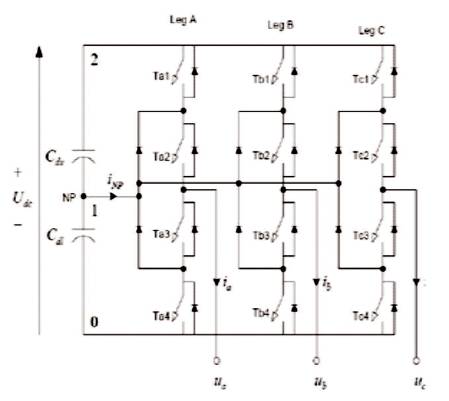
Figure 1. NPC Converter Topology
The main objective of this paper is the proposal of new modulation techniques for three phase transformerless neutral point clamped inverters to eliminate harmonics in photovoltaic systems without requiring any modification on the multilevel inverter or any additional hardware. The modulation techniques are capable of reducing the harmonics in photovoltaic systems by applying PWM (Pulse Width Modulation) and SVPWM (Space Vector Pulse Width Modulation) or converter. A multilevel power conversion concept is based on the combination of Neutral-Point- Clamped (NPC) and floating capacitor converters. In the proposed scheme, the voltage balancing across the floating capacitors is achieved by using a proper selection of redundant switching states, the input source is PV System. The output voltage waveforms in neutral point clamped inverters can be generated at low switching frequency losses with high efficiency and low distortions. This paper presents the switching pattern to generate symmetrical gating signal to control NPCVSI (Neutral Point Clamp Voltage Source Inverter) using matlab/simulink.
In recent years, the increasing demand for energy has stimulated the development of alternative power sources such as photovoltaic cell (PV) modules, fuel cells, and wind turbines. The PV modules are particularly attractive as renewable source because of its relative small size, noise, less operation and simple installation [6]. Multilevel inverter technology has emerged recently as a very important alternative in the area of high power medium voltage energy control. In this paper, the main objective is to eliminate THD (Total Harmonic Distortion) for PV System with NPC inverter. The main proposal of multilevel inverter concept is based on the combination of the multilevel of inverter and Neutral Point Clamped inverter (NPC). In PV cell or modules, if any one of the output voltage is very low, it should step up the voltage and then it's converted into an AC voltage[7]. A transformerless three phase (NPC) inverter is used in this paper to convert DC current into AC current. PV system is used for many advantages as it is a very attractive energy source in that time, but it gives very low output voltage and hence it cannot be used for high power application. To overcome this problem, the connection of PV modules is created employing a multilevel converter to increase the higher efficiency of the system. Multilevel converters have the advantage of clamping the voltage, which prevents the need of fast switching [2]. Neutral point clamped inverter three level converters has the increased complexity in the control of it. The output waveform has three – level PWM inverter in terms of total harmonic distortion without the use of bulky expensive and dissipative passive filter. Several control techniques are proposed in this paper to control the THD. Techniques used are Pulse Width Modulation and Space Vector Modulation [1]. SVM techniques uses switching states to control the THD. A carrier based PWM techniques like phase shifted and level shifted PWM are implemented to generate the waveform of load voltage and load current with the reduction in THD. This paper proposes the simulation of three-level diode clamped inverter employing a sine wave which is compared with the carrier signal to generate pulses for the switches.
Multilevel converters have a good choice for medium and high-voltage application multilevel converters; the traditional solution has been to connect semiconductors in series to withstand high voltages. This requires fast switching to avoid unequal voltage sharing between the devices. Multilevel converters have the advantage of clamping the voltages, which prevents the need of fast switching [8] . As wind turbines and Photovoltaic system are increasing in power ratings, multilevel converters can be well suited in such applications [4]. Neutral point clamped three- level converter challenges with the NPC three-level converter with the increased complexity in the control of it. Converter topology and a numerous control methods are presented [19]. Each DC generator consists of PV system connected in series and/or in parallel, thus obtaining the desired output voltage and current. Three-phase system can be realized by delta or WYE connection of three single-phase systems [5]. However, the number of levels increase the complexity, and the cost of the system while reducing its switching frequency in comparison with two level converters. Three level diode clamped inverter consists of twelve switches and six fast recovery diode which are shown in Figure 1. The converter studied in this paper is a NPC three level converter with three bridge legs. Three-level means that each bridge leg A, B, C can have three different voltage states converter topology which can be seen in Figure 1. Switch 1 and 3 on each leg are complementary which means that when switch 1 is on, switch 3 is off and vice versa. Switches 2 and 4 are the other complementary switching pair.
Figure 1. NPC Converter Topology
The combination of states for the bridge legs are given in the space vector Table 1. Space vector 210 means that bridge leg A is in state 2, leg B in state 1, and leg C in state 0. Some of the switching states give the same space vector as is seen for the inner vectors. All the modulation strategies discussed in the subsequent chapters use combinations of these switching states [2]. The difference between the modulation strategies is the combination of states and their respective extent. The output phase voltage and line voltage of three phase neutral point clamped inverter are shown in Figures 2 and 3 respectively.
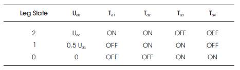
Table 1. Bridge Leg Voltage at Different Combinations of Switch States
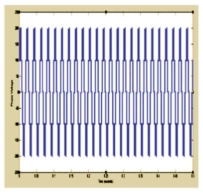
Figure 2. Output Phase Voltage of Three Phase NPC Inverter
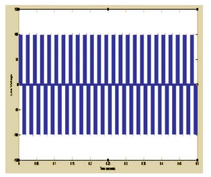
Figure 3. Line Voltage of Three Phase NPC Inverter
Switching strategies for a three-level converter is controlled by three-medium vector modulation. Three-medium vectors are PWM and SVPWM. It is a popular modulation method for converter, due to its low harmonics. One of the most basic PWM methods is known as carrier-based PWM, which generates the control pulses by comparing a high frequency carrier signal to a low frequency reference signal [15]. In the simplest version, a sinusoidal reference representing the desired line-to-neutral voltage is compared to a triangular carrier signal [8],[9]. A popular research area for carrier-based PWM is to develop different signals to add to the reference signal. A space vector is that phase A, B and C has a permanent position to each other in the vector space, phase shifted with 120 degrees [18]. The two modulation strategies used in this paper are:
A number of Pulse Width Modulation (PWM) schemes are used to obtain variable voltage and frequency supply. The most widely used PWM schemes for three-phase voltage source inverters are carrier based sinusoidal PWM and Space Vector PWM (SVPWM). In inverter, the output voltage can also be adapted by applying a controller itself in the inverter [10]. The better method for powerful output can be done by Pulse Width Modulation. In this method, a constant DC input voltage is disposed into the inverter also an unflappable AC output voltage is accessed by regulating the on and off duration of the inverter. PWM techniques are represented by fixed amplitude pulses [13], and it is the most suitable method of controlling the output voltage. The advantages are:
The major disadvantage of PWM method is that SCR are costly as they should carry low turn-on and turn off times. To archive the output voltage control of inverter and to minimise the harmonics present by the width of these pulses [16], many PWM techniques are employed which are given below.
It was first introduced by the German researchers in the mid 1980s. SVM technique can maximize the output voltage, and also reduce the switching number at the same carrier frequency of the PWM method. An increasing trend of using Space Vector PWM (SVPWM) is because of their easier digital realization and better DC bus utilization [10] . Moreover, it gives a higher output voltage for the same DC bus voltage, lower switching losses, and better harmonic performance in comparison to carrier based sinusoidal pulse width modulation [14]. The Space Vector PWM (SVPWM) is used to control the three-level inverter output voltages and there are 19 possible space vectors as shown in Figure 4. One zero vector (V0) with three switching possibilities, six long vectors (V1, V2, V3, V4, V5, and V6), six medium vectors (V7, V8, V9, V10, V11,and V12) and six small vectors (V13, V14, V15, V16, V17, and V18) with two switching possibilities each, from which total to 27 possible switching combinations are obtained [17],[20].
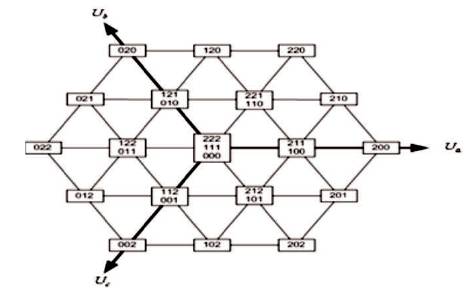
Figure 4. Space Vector Diagram for a Three-Level Converter
A lot of vectors to choose for a three-level converter, and the normal way of solving this is to choose the three vector states closest to the reference vector when using Space Vector modulation. Reason for this technique is that the harmonic distortion will be the lowest this way [12] .
Table 2 shows how the switching pattern should be designed to minimize the number of switching transitions. This switching pattern is used for all the vectors used, so the redundancy is maximized. The major drawback of using all of the vectors is that there will be an increase in the switching losses. Figure 5 shows the switching pattern of three medium vectors.
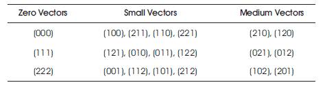
Table 2. Space Vector for Three-Levels
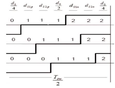
Figure 5. Switching Pattern for Three-Medium Vector
LC filter output voltage wave is synchronized with the output voltage. So the PWM inverter will inject ripple current in the output. LC filter is connected to remove high switching frequency components from output current of inverter [3] , where L=20e-3 , C= 50e-6 . The value of L is designed based on current ripple. Smaller ripple results in lower switching and conduction losses. The capacitor C is designed based on reactive power supplied by the capacitor at fundamental frequency.
In this paper, the proposed modulation techniques for three Phase transformerless NPC inverter are used to validate the proposal of eliminating the THD in PV system. The simulation parameters are shown in Table 3. Three level NPC inverter are used for the IGBT 12 pulse. Different PWM techniques are compared on the output voltages amplitude. The simulation parameters are carrier frequency=10000, input voltage of PV=200 V modulation index m=1, variable load (phase), and the nominal frequency is 50 Hz.
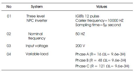
Table 3. Simulation Parameters
The module of three phase inverter is designed by MATLAB simulation. The module is designed by taking voltage source, which is connected to the three phase inverter. The frequency is taken as 50 Hz. The PV output is connected with IGBT type of inverter which is further connected to the LC filter. The output voltage is 200 V. They used the force commutated devices (GTO, IGBT, MOSFET). Figure 6 shows the PV System model using PWM; the controls signal frequency (FC) is taken as 50, switching frequency as 10000 Hz and modulation index is 0.9. LC filter is connected to the system which removed the harmonics. The three phase voltage current measurement block measures the output voltage and current is in volts and ampere. The three phase load is RL load which is a variable load.
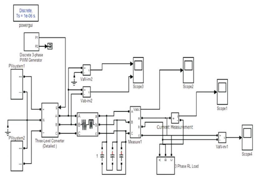
Figure 6. PV System by using PWM
The module is designed by taking voltage source, which is connected to the three phase inverter. In this module, the input voltage is taken by PV system. SVPWM gate pulse is connected to three phase NPC inverter. The LC filter reduces the harmonics. The three phase voltage and current measurement measures the voltage and current. Figure 7 shows the PV system model using SVPWM; the control signal frequency (FC) is taken as 50, switching frequency as 10000 Hz and modulation index is 0.9. LC filter is connected to the system to remove the harmonics.
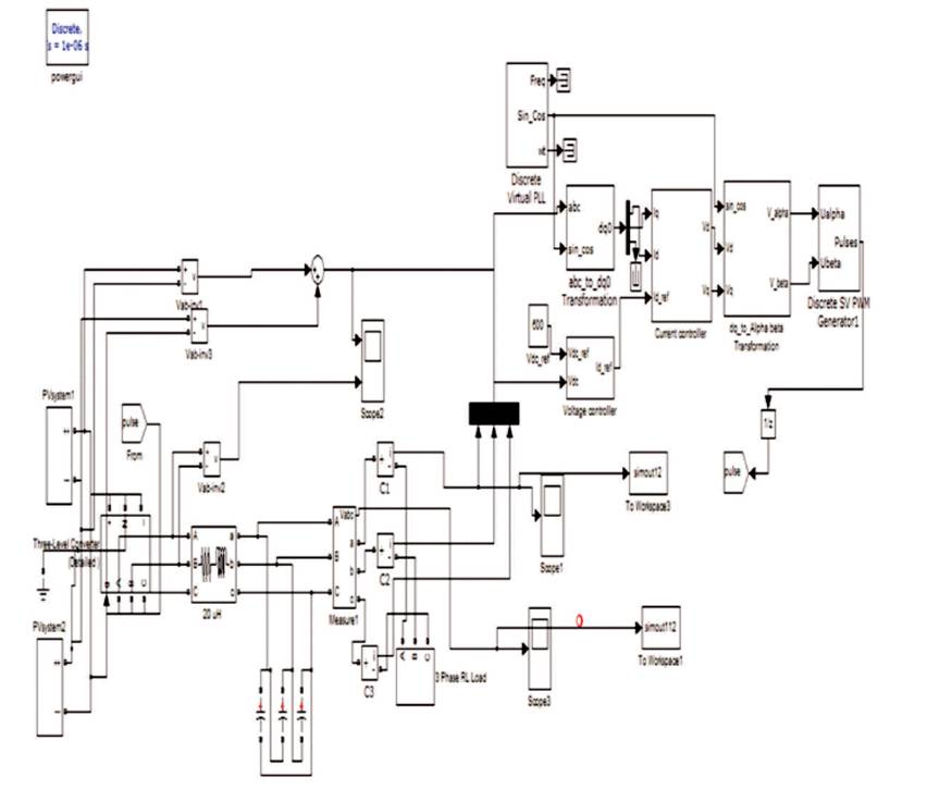
Figure 7. PV System by using SVPWM
Based on the design, the simulation of the entire system is done by MATLAB simulation. The output voltage of the three phase PWM inverter is based on the voltage controller. Figure 8 shows the source voltage of PV system. PV system gives the constant value.
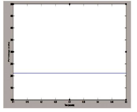
Figure 8. Output Voltage of PV
Figures 9 and 10 show the three phase load voltage and load current of the system by PWM techniques respectively.
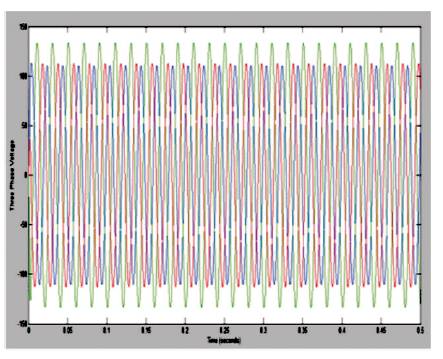
Figure 9. Three Phase Load Voltage by using PWM
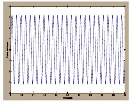
Figure 10. Three Phase Load Current by using PWM
The three phase load voltage and load current of the PV system based on the SVPWM are shown in Figures 11 and 12 respectively. By PWM, THD is 2.55. By SVPWM, THD is 1.34.
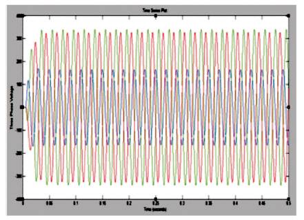
Figure 11. Three Phase Load Voltage by using SVPWM
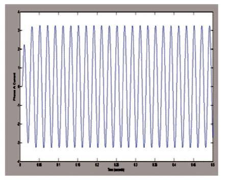
Figure 12. Three Phase Load Current by using SVPWM
In this part, some simulations have been done in order to compare the different modulation techniques. The modulation techniques reduce the THD. Fast Fourier transform analysis can be useful to show the variation of eliminating total harmonic order in inverter circuit.
Figure 13 shows the FET analysis of harmonics elimination, by using PWM techniques. The total harmonic distortion is 2.55 and the modulation index is 0.9.
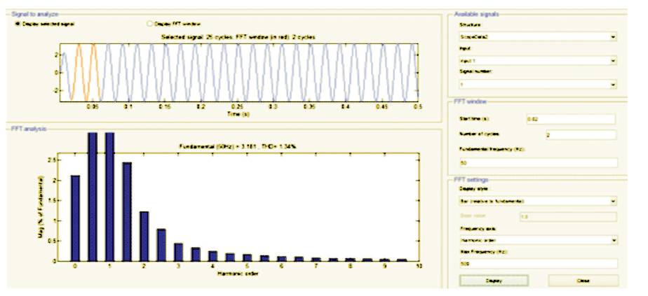
Figure 13. Harmonic Elimination from FET by PWM
Figure 14 shows the FET analysis of harmonics elimination, by using SVPWM techniques. The total harmonic distortion is 1.34 and the modulation index is 0.9.
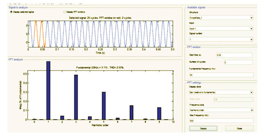
Figure 14. Harmonic Elimination from FET Analysis by SVPWM
Table 4 shows the comparison of Modulation techniques, where the THD for SVPWM is less than PWM.
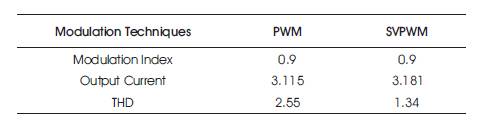
Table 4. Comparison of Three Phase Transformerless Inverter
In this paper, a PV system with NPC inverter to eliminate harmonic is presented for achieving good result. Modulation techniques are developed in such a manner that they eliminate harmonics, which uses single DC source, and PV system as DC source. In this paper, modulation techniques are designed for three phase transformerless PV system. Table 4 shows the result in terms of reducing THD. The techniques guarantee improving the behaviour of the NPC inverter in terms of THD. The two techniques PWM and SVPWM are used which gives better performance in terms of reducing the THD. The simulation result using MATLAB confirmed that the developed scheme eliminated harmonics to the entire range of operation with high efficiency. Space Vector Modulation technique is better than PWM because in SVM modulation it is digitally modulated. The following technique/scheme has several advantages which are as follows.