1. Experiment Setup
The study aimed to compare the relative thermal performances of different roof-construction designs and configurations. As such, it was essential that all construction configurations conform to identical structural designs and environmental conditions. To this end, the considerations listed below were incorporated.
1.1 Design Configurations
The structures used in this study comprised the following design configurations:
- Single metal roof, which serves as the reference configuration Figure 1.
- Double metal roof with 31/2” (8.89cm) air spacing between roofs Figure 2.
- Double metal roof, 31/2” (8.89cm) air spacing between roofs with vent opening on top roof Figure 3.
- Single Roof with Radiant Heat Reflector underneath, spaced 31/2”(8.89cm); also referred to as Roof with Radiant heat reflector Figure 4.
- The adopted construction method for double roofs is shown in Figure 5.
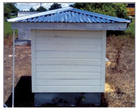
Figure 1. Traditional Single Layer Metal Roof - Reference
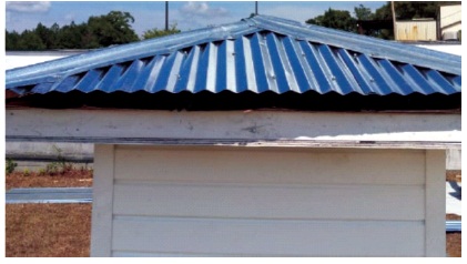
Figure 2. 1/2 Double Metal Roof, 31/2” Air Spacing
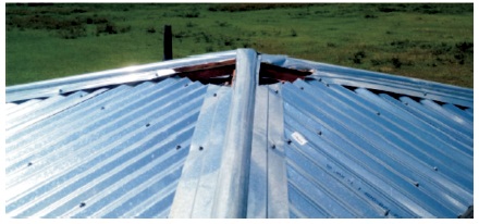
Figure 3. 1/2” Double Metal Roof, 31/2” (8.89cm) Air Spacing, with Vent Opening in Top Roof
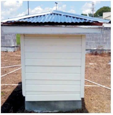
Figure 4. Single Roof with Radiant Heat Reflector Underneath - Spaced 31/2” (8.89cm
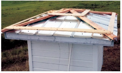
Figure 5. Double Roof Construction Method
The designs, constructions and installations of roof-support structures were identical for all test units. The goal of the support structure design was to provide significant insulation to uphold the assumption that all the heat recorded in the core interior of the roof space was solely due to the radiant heat transmitted through the roof cover. The typical interior section of the roof supporting structure is shown below in Figure 6. The interior is abundantly insulated to support the assumption that all the heat in the attic is exclusively from the roof.
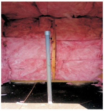
Figure 6. Typical Construction of Roof Supporting Structure
1.2 Orientation
All structures were placed in a north-south row. as shown in Figure 7. In this orientation, no structure casted shadows over the others and the rising sun affected all the structures uniformly.
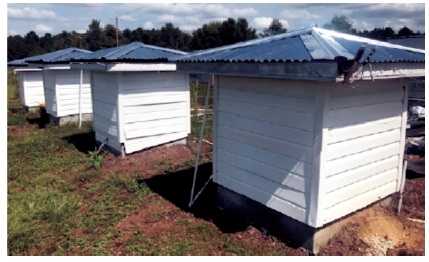
Figure 7. Test Structure in Row Layout
1.3 Sensor Locations
All temperature sensors in the core envelope structures were mounted at identical locations, i.e., the midpoint of the roof attic, midpoint between double roof space, and the open space for ambient temperature as illustrated in Figure 8.
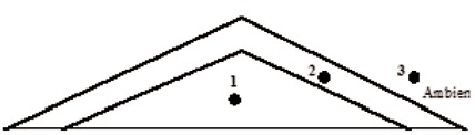
Figure 8. Temperature Sensor Locations
1.4 Sensor Type
All temperature sensors and wires were identical and ran to a common data acquisition point through conduit pipes. The sensors used were the Watlow Ring Terminal Thermocouple, Type J shown in Figure 9.
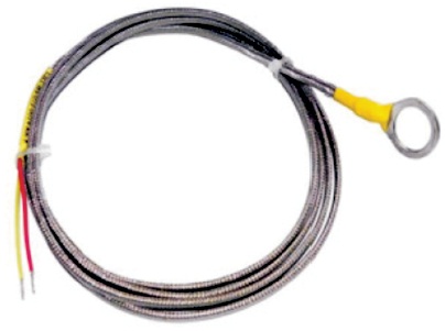
Figure 9. Temperature Sensor
2. Experimental Data
The experiment was designed around the Lab VIEW software and National Instrument (NI) data acquisition devices. Lab VIEW programs were written to collect data at the rate of two data points per minute for each sensor connected to the data acquisition device. The NI Wireless Sensor Network (WSN 3212) was the data collection device used in the experiment. Temperature data from all the sensor locations were simultaneously captured. The WSN device was located at the construction site and it wirelessly transmitted the sensor data to an Ethernet gateway (NI WSN 9791) in remote location. The temperature data collected were stored on a dedicated computer in the laboratory.
3. Results
The study examined the temperature profile in hourly intervals on 24-hour time span. The temperature data point for each sensor was captured every 30 seconds and averaged as hourly average over 60-minute period. The hourly average was further averaged over 7-day data period to obtain weekly average data, as shown in Table 1. The study analyzed that during daytime temperatures in typical SSA region is of 75 oF (24 oC) and above.
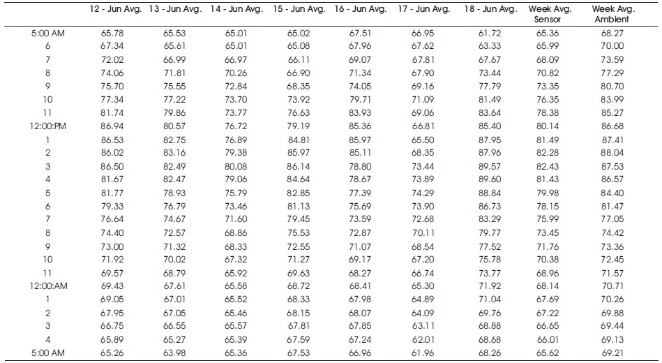
Table 1. Sample Average Temperature (oF)-Hourly and Weekly Data
The study analyzed that during daytime temperatures in typical SSA region is of 75 oF (24 oC) and above. A typical profile of ambient temperature sensor and roof sensor outputs for a single roof configuration, (i.e., the reference structure) is illustrated in Figure 10.
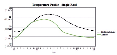
Figure 10. Sample Ambient and Interior Space Temperature (oF) Profile for Single Envelope Roof Structure
A typical temperature profile for double roof envelope constructions is shown in Figure 11. The figure shows the relative temperature (oF) ( oC) profile at sensor locations for ambient, attic interior and between roofs.
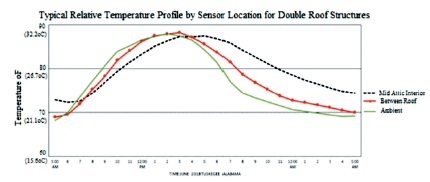
Figure 11. Sample Relative Temperature Profile (oF) at Different Sensor Locations per Figure 8
Figure 12 shows the relative magnitude of thermal energy stored in the roof attic space over a 24-hour period under identical environmental and atmospheric conditions for the different roof-envelope design configurations. The figure indicates that the best thermal performing configuration (i.e., the configuration that allowed the least amount of heat to be transmitted from the roof to the interior space over a 24-hour period) is the Roof with Radiant Heat Reflector.
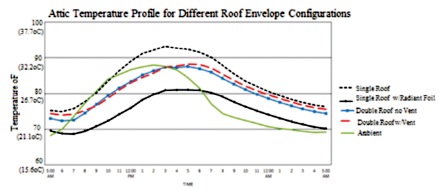
Figure 12. Temperature (oF) Profile for Different Roof Configurations
For existing homes, the radiant foil may be attached to the roof rafters of the traditional single roof attic as illustrated in Figure 13.
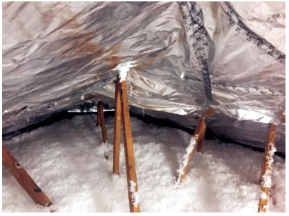
Figure 13. Radiant Heat Reflector Installed in an attic
4. Discussion
The outcome sought in this study is a representative indication of the relative costs to cool a home with solar energy under different roof-envelope design configurations. The assessment compares the traditional single roof-envelope with other roof construction configurations in terms of effectiveness to reduce the amount of radiant heat transmitted from outside environments to the building interior through the roof. The analysis considered the heat stored in the building interior over a time-period for the different roof designs and configurations and subsequently computed the relative costs to remove the heat. The computational procedure involved two primary steps, i.e.,
- Compute the heat stored in building interior through the roof only
- Compute the cost to remove the heat using solar energy
The cost considerations in the analysis include the following:
- Solar panels and cooling equipment costs (i.e., materials and installation)
- Roof (i.e., materials and installation)
- Operational costs (Electricity)
4.1 Interior Environment
The thermal performance results obtained in this project are directly based on the roof structure dimensions as shown in Figure 14, i.e.,
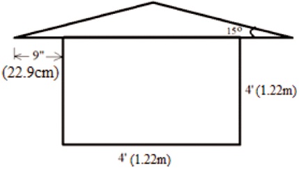
Figure 14. Experimental Roof Dimensions
- Roof base: 4'x4'x4' (1.2mx1.2mx1.2m).
- Roof type: hip with 9” overhang
- Roof pitch: 15o
In the following analyses, the results are scaled for larger realistic space environment with the following assumptions:
- Area of home can scale from 16ft (1.49m ) to 800ft2 (74.32m2)
- The thermal performance of the experimental 4'x4' (16 ft2) [1.22m x 1.22m (1.49m2)] space can linearly translate to an 800ft2 (74.32m ) space.
- Prevailing environmental and ambient conditions of the 16 ft2 experimental space are identical to the 800ft2 (74.32m2) space.
For 800ft2 (74.32m2) home, the assumptions for this scenario are the following: Heat to be removed from the attic by the cooling unit is solely due to the roof envelope. According to Kylili et al. (2016) and Cengel, (2006) the amount of heat-gain in the attic of a building envelope due to solar radiation is given by

Where,
- A= Area of roof (ft2)
- hconv = interior attic still air convective heat coefficient =1.08 Btu/h ft2 (Engineering Tool box.com)
- Ti(t) = hourly attic temperature reading in roof over a 24-hour period

- Tcomfort = desired comfort temperature 75 oF (23.9 oC) comfort
4.2 Summing up the Heat Over Time
In Equation (1), the term Ti(t) represents the average attic temperature for each hour over the specified time-period (i.e.,24-hour). The difference between the attic temperature profile and the comfort level profile (ΔQ), designated by represents the accumulated radiant heat to be removed from the building interior in other to maintain the reference comfort temperature. The profiles for a single envelope roof, and the Roof with Radiant Heat Reflector are compared in Figure 15.
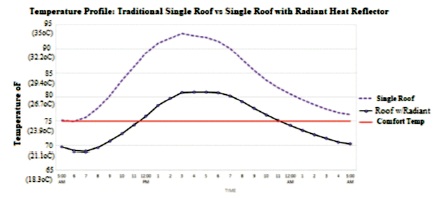
Figure 15. Relative Stored Heat – Traditional Single Roof Vs Single Roof Over Radiant Heat Foil With 31/2” (8.89cm) Air Space Between
The figure shows that using the Roof with Radiant Heat Reflector reduces the attic peak temperature by about 12.26 oF. Some researchers have (Suman & Srivastava, 2009;Bortoloni et al., 2017) reported comparable results in their roof related studies.
Figure 15 is separated into individual profiles as shown in Figures 16(a) and Figure 16(b), respectively. The stored heat to be removed (ΔQ), is bound by the temperature profile and the 75 oF (23.9 C) comfort line as indicated by the hatch lines.
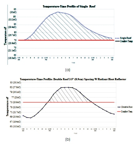
Figure 16. (a) Stored Heat for Removal – Single Envelope Roof (b) Stored Heat for Removal – Roof with Radiant Heat Reflector
Using the Matlab trapezoidal integration method illustrated in Figure 17, the bounded area can be computed. The trapezoidal integration method approximates the integration over a given interval by breaking the area down into trapezoids with more easily computable areas.
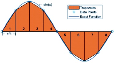
Figure 17. Illustration of Matlab Trapezoidal Integration Method
The function may be mathematically presented (Numerical Integration and Differentiation, 2019) as:
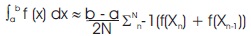
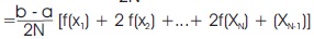
Where, the spacing between each point is equal to the scalar value (b-a)/N. In the 24-hr period used in this computation, a=0, b=24 and N=24. The output of the computation is the product of hour and temperature (hoF). Using the Matlab trapezoidal integration method, the function ; represents the radiant heat energy ΔQ to be removed. ΔQ for the different roof configurations investigated are computed respectively as:
ΔQ for single roof = 425.76 h
ΔQ for Roof with Radiant Heat Reflector = 144.7 h
ΔQ for double roof without central vent = 250.2 h
ΔQ for double roof with central vent = 317.04 h
4.3 Detail Computation
The computational process for the performance measures for the different configurations is as summarized below:
Heat gain q = (Asan, 2006)
Where,
hconv = 1.08 according (Engineering Tool box.com)
A = 800sqft = (74.32m2)
q = Qi In this study, we assumed that:
Total Heat gain q= Δ Qi Btu (due totally to the radiant conv heat through the roof to the interior)
Heat gain per hour = q/24
Allowing 25% for exigency in designing the solar cooling system:
Maximum heat gain/hr. = q*1.25/24 BTU/Hr.

4.4 Number of Solar Panels Computation
Assumptions:
The A/C unit in the solar cooling system design to remove stored heat has SEER = 13

Solar panel rating = 150W/panel. Average sun-hours per day over one-year period = 6Hr.
Hence, the number of solar panels required to produce the designed cooling power
= (Design Power (watt.hr)) / [(Watt/Solar Panel) * (Sun-Hr./d ay )]
Table 2 summarizes the above computations.
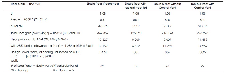
Table 2. Energy Requirement and Number of Solar Panel Computation
4.5 Unit and Fixed Costs
Fixed and operational cost are considered in the financial merits of each design configuration. Fixed cost includes materials, equipment costs and installation costs. Operational cost includes energy costs associated with o o cooling the interior environment to 75 F (23.9 C). Local vendors provided data used for the computations. Vendors provided installed costs as typical in their respective trades. Installed cost rate includes material and labor costs combined. The cost data used in the calculation are:
- Solar panel installed cost rate: $3.42/watt
- Cooling unit (A/C) installed cost rate: $0.20/Btu
- Regular Roof Installed cost rate: $10/ft2.
- Regular Roof Installed cost rate plus Radiant Heat reflector: $15/ft2.
- Double Roof Installed cost rate: $25/ft2.
- Double Roof with vent installed cost rate: $26/ft2.
These values were used in the computation of solar panels, A/C unit, and roof installations costs as summarized in Table 3.
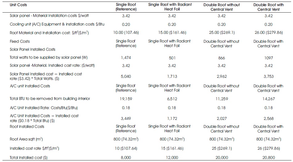
Table 3. Fixed Cost Computation
4.6 Operating Costs
The framework in computing the operating cost is that the house built with the traditional single envelope roof stands next to the other houses built with different design configurations. All are presumed cooled to 75oF (23.9 C)24hrs/day and 365 days/yr.The electricity rate data used in the computation is $0.2747/KWH. This rate is chosen to reflect the relatively higher electricity rates anticipated in high temperature regions of the world including SSA. Hence,
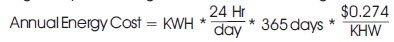
The operating cost computation is summarized in Table 4.
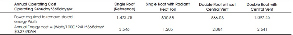
Table 4. Operating Cost Computation
4.7 Cost Projection
In Table 5, the fixed costs and operating costs are combined and projected into the future to identify the break-even point for the single envelope roof versus other design configurations under identical operating conditions.
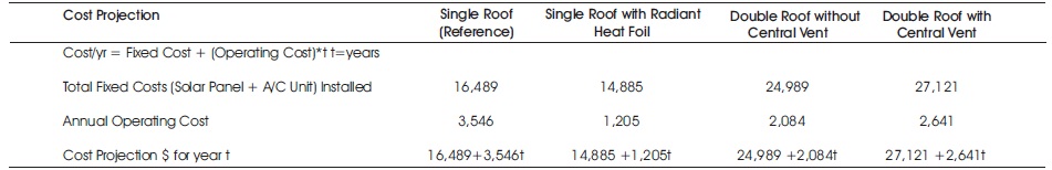
Table 5. Cost Projection Computation
The following equations are results of the cost ($) projection computations:


Where t denotes number of years.
Equations (6) through (8) are plotted in Figures 18-20, for comparison of break-even points relative to the traditional single roof.
Figure 21 shows the peak temperature difference between an experimental single roof attic compared with an actual roof attic with radiant heat reflector [31/2” (8.89cm) air space separation between roof and reflector] in the similar geographical location, in terms of decreasing the radiant heat ingress into building interior through the roof envelope.
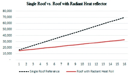
Figure 18. Fixed and Operating Cost Comparison Projection- Standard roof vs. Roof with Radiant Heat reflector
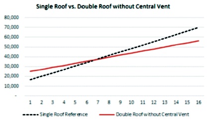
Figure 19. Fixed and Operating Cost Comparison Projection- Standard roof vs Double Roof without Central Vent
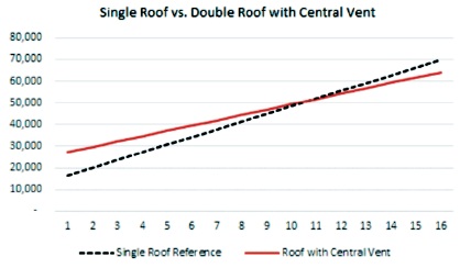
Figure 20. Fixed and Operating Cost Comparison Projection- Standard roof vs Double Roof with Central Vent
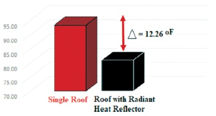
Figure 21. Impact of Radiant Heat Reflector in Attic Temperature Reduction
Conclusion
The paper recognized the long-standing tradition of roof construction with Zinc and other metals in urban and suburban areas of Sub Sahara Africa (SSA). The lack of consistent use and availability of insulation in the building constructions give rise to energy inefficient buildings that do not lend to the use of solar energy for cooling. Given the very dim prospect that the building materials and practices will change or that insulation materials, if available and affordable, can be incorporated into the traditional construction practices, the paper explored options within these constraints for new envelope roof designs that will make cooling with solar more financially feasible. The cost analyses conducted show that if the goal of the roof construction design is to reduce the radiant heat ingress into building interior for solar cooling purpose, incorporating radiant heat reflector in the roof construction is the most effective and least costly of the different building envelop designs investigated.
In a similar study involving single corrugated zinc and double roof in a desert environment, Abraham and George, (2007) observed that heat transfer through metalic roofs can be dramatically reduced through the use of inexpensive highly reflective sheets. Additionally, MacDonald et al. (2001), cited the work of Cummings et al. (1991) with respect to ceramic coatings on asphalt shingle roof where impactful decrease in energy usage was observed. In the referenced study, the attic temperature was reported to drop from about 110oF to 88oF. The work presented in this paper adds to the body of knowledge in the field of radiant barrier by providing a contextual quantitative value of the extent to which the use of reflective sheets may impact radiant heat ingress to the interior of metal roof buildings. In this study, using radiant heat barrier as a second layer in the roof construction reduced the attic peak temperature of a traditional single o roof envelope by 12.26oF. Figure 18 shows that it takes about the same or less initial capital cost to implement the radiant heat reflector configuration while also illustrating lower operational costs with time. This study therefore suggests strongly that the application of solar energy for cooling in predominantly hot climates is technically and financially feasible to the extent that the radiant heat transmitted and stored in interior environments is minimized. This study confirms that radiant heat ingress into building interior from building envelopes (roof and walls respectively) can indeed be minimized through creative designs and configurations as implemented and tested in this study.